- All
- Product Name
- Product Keyword
- Product Model
- Product Summary
- Product Description
- Multi Field Search
Views: 0 Author: Site Editor Publish Time: 2026-10-20 Origin: Site

Automotive grilles are highly visible, structurally complex components that define a vehicle's front-end aesthetics and manage critical airflow. A single surface defect results in a rejected part. Manufacturing these large, intricate parts requires balancing aesthetic perfection with structural integrity and aggressive cycle times. Poor mold design leads to warpage, visible weld lines, sink marks, short shots, and high scrap rates, destroying production margins.
Optimizing an automotive grille injection mold requires moving beyond basic tooling principles. This guide details the advanced design frameworks, gating strategies, thermal management techniques, and defect-prevention methodologies required to evaluate, design, and procure high-yield tooling for automotive exterior components.
Establishing baseline requirements for automotive grilles requires a deep understanding of polymer behavior and mechanical assembly. These components demand absolute dimensional stability. They must integrate flush with adjacent fascia, headlamps, and hood lines. Any deviation in shrinkage or warpage creates uneven panel gaps that fail quality control immediately. High impact resistance is also mandatory. The grille serves as the first point of contact for road debris and minor collisions. The tooling must facilitate optimal molecular orientation during the injection phase to maximize the polymer's structural integrity, especially when molding impact-modified polypropylene or PC/ABS blends.
Class-A surface requirements dictate a zero-tolerance policy for cosmetic defects. Exterior vehicle components undergo rigorous visual inspections under specialized zebra lighting tunnels on the assembly line. Flow marks, sink marks, blushing, and flash are immediate causes for rejection. Achieving this flawless finish requires precise control over cavity pressure, mold temperature, and venting. The steel surface itself must be polished to an SPI A-1 or A-2 standard. Any microscopic imperfection in the tool steel transfers directly to the molded plastic, ruining the aesthetic.
Modern vehicle designs introduce extreme tooling complexities. Deep ribs, intricate honeycomb meshes, and integrated active grille shutter (AGS) housings create tortuous flow paths for the molten plastic. These complex geometries increase the risk of air traps and short shots. They also complicate the ejection process. Removing a deep-draw honeycomb structure from the mold without causing drag marks or part deformation requires exact draft angles and highly balanced ejection systems. You cannot force a part out of the core; the ejection mechanics must be perfectly distributed.
Maintaining tight tolerances across a massive surface area is the ultimate test of an automotive grille mold. A front grille often spans the entire width of a vehicle, sometimes exceeding 1.5 meters. Polymers naturally shrink as they cool. Managing this shrinkage over a large, curved surface requires advanced thermal mapping. If the center of the grille cools at a different rate than the outer edges, the part will warp. This dimensional instability ruins the fit and finish, making assembly impossible.
| Defect Type | Common Root Cause in Grille Molds | Shop Floor Tooling Optimization |
|---|---|---|
| Weld Lines | Colliding melt fronts from multiple simultaneous gates. | Implement sequential valve gating to cascade the flow front. |
| Sink Marks | Excessive mass at rib or boss intersections. | Maintain rib thickness at 50-60% of the nominal wall. Core out thick sections. |
| Warpage | Uneven cooling rates across large surface areas causing internal stress. | Utilize conformal cooling channels in complex geometries to balance Delta T. |
| Short Shots | Inadequate venting in deep honeycomb meshes or insufficient injection pressure. | Add perimeter and ejector pin venting; optimize pack pressure profiles. |
| Drag Marks | Insufficient draft angles on deep ribs or textured surfaces. | Increase draft to minimum 1.5°, adding 1° per 0.025mm of texture depth. |
Mastering wall thickness, ribs, and boss proportions is the foundation of a high-quality front grille mold. Thick sections cool slower than thin sections. This differential cooling pulls material inward, creating visible sink marks on the opposite face. To prevent this on Class-A surfaces, engineers follow a strict rule-of-thumb. Rib thickness should never exceed 50 to 60 percent of the adjoining nominal wall thickness. For example, if the grille's main fascia has a nominal wall of 3.0mm, the base of any supporting rib must not exceed 1.5mm to 1.8mm. This ratio provides necessary structural support while mitigating localized shrinkage.
Mounting boss design requires similar scrutiny. Bosses are essential for attaching the grille to the vehicle frame. However, a thick, standalone boss causes a massive sink mark. You must use gussets. Gussets provide structural rigidity and distribute mechanical loads without adding excessive mass. When designing thick sections that cannot be avoided, engineers must core them out. Coring removes unnecessary material from the hidden side of the part. This maintains the grille's impact resistance while ensuring uniform cooling and preventing surface defects.
Draft angles and parting line placement dictate the success of any automotive exterior trim mold. The parting line is where the two halves of the mold meet. You must optimize this placement to hide potential flash on non-visible edges. Modern grilles feature complex 3D contours. The parting line must follow these contours precisely. Stepped or curved parting lines require high-precision 5-axis CNC machining to ensure a perfect shutoff. Even a microscopic gap of 0.02mm will allow pressurized plastic to escape, creating flash that requires manual trimming.
Increased draft angles are mandatory for large exterior components. Draft allows the part to release from the mold cavity without friction. For smooth surfaces, a minimum draft of 1.5 to 2 degrees is standard. However, automotive grilles often feature textured surfaces or deep draws. These require aggressive draft angles, often exceeding 3 degrees. A general engineering guideline adds 1 degree of draft for every 0.025mm of surface texture depth. Failing to provide adequate draft results in scuffing, drag marks, and severe cosmetic damage during ejection.
Managing undercuts requires strategic Design for Manufacturability (DFM). Automotive grilles rely on dozens of snap-fits and mounting clips for assembly. These features create undercuts that prevent the part from ejecting straight out of the mold. The most robust solution is leveraging shutoffs, also known as pass-through cores. Shutoffs use interlocking steel geometries between the cavity and core to form the undercut. This eliminates the need for moving parts. It drastically reduces tool complexity, lowers maintenance requirements, and extends the life of the mold.
When shutoffs are not geometrically possible, engineers must use lifters or sliders. Angled lifters move diagonally during ejection to release internal undercuts. Hydraulic sliders pull steel cores away from the part's exterior before the mold opens. Sliders are highly effective but add significant mechanical complexity. They require precise timing, dedicated cooling circuits, and constant lubrication. Analyzing the mechanical trade-offs between lifters and sliders is critical. You must balance initial tooling costs against long-term maintenance requirements on the production floor.
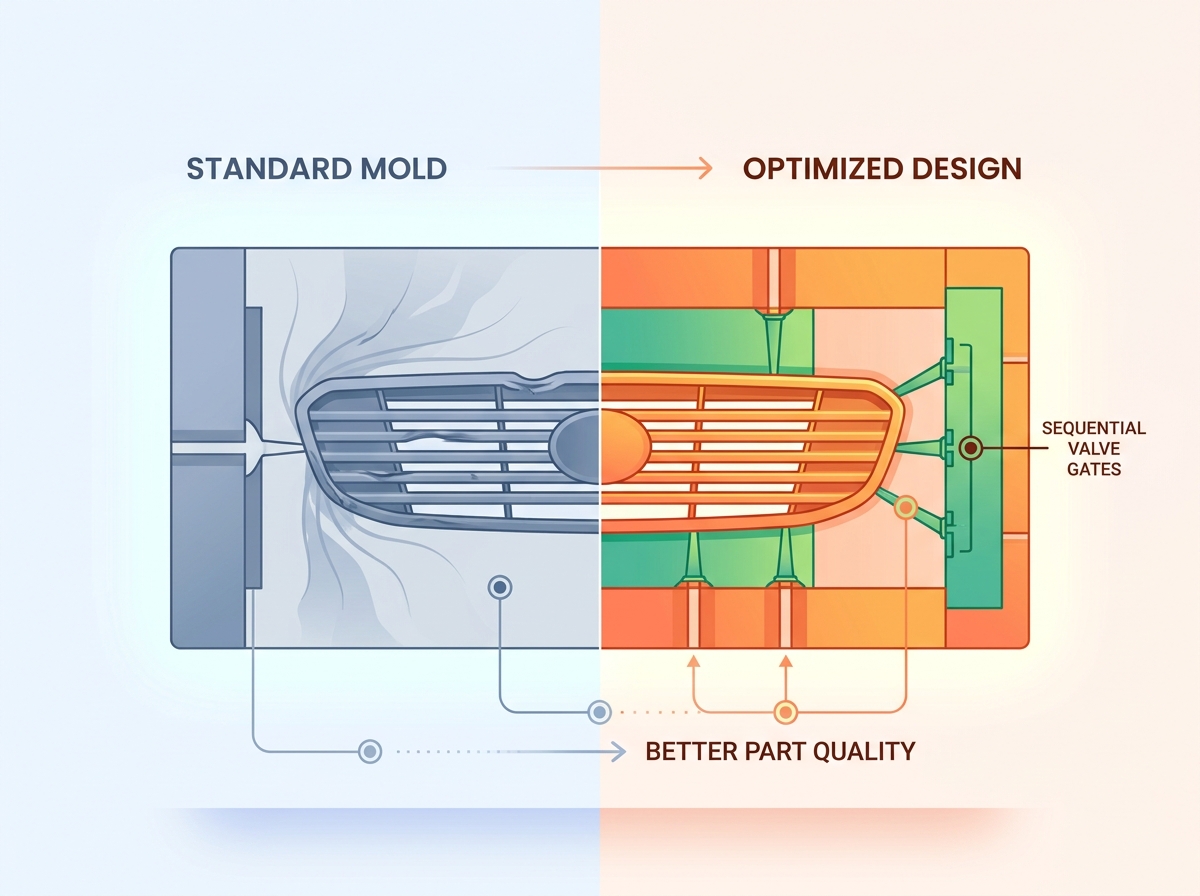
Standard hot runner systems fail when molding large automotive grilles. A standard system opens all gates simultaneously. This injects molten plastic into the cavity from multiple locations at once. As these separate melt fronts expand, they eventually collide. The point of collision forms a weld line. On a Class-A surface, a weld line is a critical defect. It disrupts the visual finish and creates a localized structural weakness. For parts exposed to high impact and vibration, these weak points are unacceptable.
Eliminating these defects requires a sequential valve gate mold. This advanced system uses pneumatic or hydraulic pins to control the flow of plastic at each individual gate. Instead of opening all gates at once, the system opens them in a programmed sequence. The process starts at a primary central gate. As the melt front flows past a secondary gate, that specific valve pin retracts, adding fresh plastic to the moving flow front. This cascade molding technique prevents melt fronts from colliding head-on. It pushes potential weld lines to hidden, non-critical areas or eliminates them entirely.
Pressure drop management is critical when designing an injection mold for car grille. The plastic must travel long distances through the mold cavity. As it flows, it loses pressure and temperature. If the pressure drops too low, the extremities of the grille will suffer from underpacking, leading to sink marks and dimensional variations. Engineers must precisely size runner channels and gate drops. Balancing the flow ensures uniform cavity pressure. This prevents overpacking near the injection points and guarantees adequate material density at the furthest edges of the part.
Strategic venting is non-negotiable for complex grille meshes. As molten plastic fills the mold, it displaces the air inside the cavity. If this air cannot escape, it becomes compressed. Compressed air superheats, causing diesel burns that scorch the plastic and damage the tool steel. Trapped gas also causes short shots and internal voids. Intricate honeycomb sections are notorious for trapping air. Engineers must implement comprehensive perimeter venting along the parting line. Vent depths typically range from 0.015mm to 0.02mm for polypropylene to allow gas to escape without flashing the plastic. Additionally, ejector pin venting is required in deep pockets. Grinding microscopic flats on specific ejector pins allows gas to escape while keeping the plastic contained.
| Gating System | Melt Flow Control | Weld Line Risk | Best Application |
|---|---|---|---|
| Cold Runner | None. Relies entirely on machine injection pressure. | Extremely High. Multiple collision points. | Small, hidden structural brackets. Not suitable for grilles. |
| Standard Hot Runner | Simultaneous fill from all gate drops. | High. Melt fronts collide between gates. | Medium-sized parts where weld lines can be hidden. |
| Sequential Valve Gate | Precise, cascaded opening of individual pins. | Zero to Minimal. Flow front is continuous. | Large Class-A exterior panels, front grilles, bumpers. |
Inefficient cooling dictates the profitability of an injection molding program. Cooling time represents the largest single component of the molding cycle, often accounting for 60 to 70 percent of the total time. Slow cooling destroys production throughput. More importantly, inefficient cooling is the primary culprit behind differential shrinkage and warpage. If a massive automotive grille cools unevenly, internal stresses build up within the polymer matrix. Once the part is ejected, these stresses release, causing the grille to twist and deform out of tolerance.
Conformal cooling channels provide a massive advantage over traditional baffle systems. Traditional cooling relies on straight water lines drilled through the steel block. These straight lines cannot reach deep core pins or follow the curved contours of a modern grille. Baffles and bubblers attempt to push water into these hard-to-reach areas, but they suffer from low flow rates and poor thermal transfer. The result is hot spots within the tool that extend cycle times and cause localized warpage.
Conformal cooling solves this by utilizing 3D-printed metal inserts, typically manufactured via Direct Metal Laser Sintering (DMLS). These inserts feature internal cooling channels that perfectly mimic the exact contour of the grille geometry. The water flows equidistant from the molding surface at all points. This technology reaches deep into complex mesh areas and isolated core pins. The return on investment for conformal cooling is substantial. It drastically reduces cycle times by extracting heat faster and more efficiently.
Mitigating warpage relies entirely on uniform temperature distribution. Balanced thermal extraction across both the cavity and core halves is mandatory. If the cavity side runs hotter than the core side, the part will warp toward the hotter surface upon ejection. Advanced thermal mapping ensures that coolant flow rates and temperatures are optimized for every zone of the mold. This uniform cooling guarantees that the polymer shrinks evenly in all directions. It locks in the structural integrity of the part and maintains the critical assembly tolerances required for automotive manufacturing.
Upfront CAD and CAE validation separates successful tooling programs from costly failures. Moldflow analysis is a mandatory step before cutting any steel. Simulating the injection process allows engineers to visualize the exact behavior of the molten plastic inside the cavity. This simulation identifies potential air traps, predicts weld line locations, and highlights areas prone to high shear stress. It allows the engineering team to optimize gate locations, adjust runner diameters, and determine the precise clamping force required to keep the mold closed during injection.
Resin-specific rheology plays a major role in tool design. Different polymer blends behave differently under heat and pressure. A high-flow Polypropylene (PP) will fill a mold much easier than a viscous PC/ABS or ASA blend. CAE tools analyze the specific rheological data of the chosen resin. This data helps engineers apply precise windage to the mold CAD. Windage is the intentional scaling of the mold cavity to compensate for polymer shrinkage. Applying the correct shrinkage compensation ensures the final molded grille meets exact dimensional specifications.
Structural analysis is required to calculate ejection forces. Automotive grilles have massive surface areas. As the plastic cools and shrinks, it grips the core half of the mold tightly. A vacuum also forms between the plastic and the polished steel. Overcoming this friction and vacuum requires immense force. Simulation verifies that the ejector pin placement, size, and surface area are sufficient to push the part off the core without causing deformation, stress whitening, or pin push marks on the Class-A surface. You must ensure the ejection system is perfectly balanced across the entire geometry.
Evaluating steel grades is a critical financial and engineering decision. The choice of tool steel dictates the mold's lifespan, maintenance schedule, and ability to hold tight tolerances over hundreds of thousands of cycles. Standard P20 steel is a pre-hardened material suitable for lower production volumes or less abrasive resins. It is easier to machine, which lowers initial tooling costs. However, P20 lacks the durability required for high-volume automotive production and will eventually show wear on parting lines and shutoffs.
Hardened H13 tool steel is the industry standard for high-volume grille molds. H13 offers exceptional toughness and resistance to thermal fatigue, typically hardened to HRC 48-52. It withstands the constant heating and cooling cycles without cracking. For programs utilizing abrasive glass-filled resins or polymers that produce corrosive outgassing, premium stainless steel, such as 420SS, is required. Stainless steel prevents cavity degradation and maintains its polished finish much longer than standard carbon steels.
| Steel Grade | Hardness (HRC) | Primary Characteristics | Ideal Grille Mold Application |
|---|---|---|---|
| P20 | 28 - 32 | Pre-hardened, easy to machine, lower cost. | Low-volume prototypes or non-visible structural backing. |
| H13 | 48 - 52 | High toughness, excellent thermal fatigue resistance. | High-volume production cores and cavities. |
| 420SS | 48 - 52 | Corrosion resistant, holds high polish. | Molding corrosive resins (PVC) or requiring SPI A-1 finish. |
Surface treatments and polishing elevate the final part quality. Achieving SPI A-1 or A-2 finishes is mandatory for grilles that will be chrome-plated or painted with high-gloss finishes. This level of polish requires diamond buffing and adds significant time to the tool build. Furthermore, specialized coatings are applied to high-wear moving components. Titanium Nitride (TiN) or Diamond-Like Carbon (DLC) coatings are frequently applied to lifters, sliders, and guide pins. These coatings reduce friction, prevent galling, and ensure smooth mechanical operation over the life of the tool.
Execute the following steps to ensure your next tooling program delivers flawless parts on schedule:
A: A sequential valve gate mold is the optimal strategy. It uses programmable pins to open gates in a specific cascade sequence. This controls melt flow fronts, balances cavity pressure, and completely eliminates cosmetic weld lines on highly visible Class-A surfaces.
A: Sink marks are prevented by maintaining uniform wall thickness. Engineers must keep rib and boss thickness to 50-60% of the adjoining nominal wall. Utilizing proper gusseting for structural support instead of thick, solid masses prevents localized shrinkage during the cooling phase.
A: Conformal cooling uses 3D-printed channels that follow the exact contours of the part. It reaches complex geometries and deep cores that traditional straight-line drilling cannot. This significantly reduces cycle times and prevents warpage caused by uneven thermal extraction.
A: A minimum draft of 1.5 to 2 degrees is required for smooth surfaces. For textured grilles, you must add an additional 1 degree of draft for every 0.025mm of surface texture depth to prevent scuffing and drag marks during ejection.
A: The preferred DFM approach uses shutoffs (pass-through cores) to form undercuts without moving parts. When shutoffs are not geometrically feasible, precision angled lifters or hydraulic sliders are implemented to release the undercuts before part ejection.
A: Hardened H13 tool steel is the standard for high-volume production due to its toughness and thermal fatigue resistance. For abrasive resins or corrosive outgassing, premium 420 stainless steel is utilized to maintain cavity integrity and high-gloss polish.