- All
- Product Name
- Product Keyword
- Product Model
- Product Summary
- Product Description
- Multi Field Search
Views: 0 Author: Site Editor Publish Time: 2026-10-20 Origin: Site

The automotive industry’s aggressive shift toward lightweighting, component consolidation, and enhanced aesthetic integration demands manufacturing processes that eliminate secondary assembly operations. Engineering teams face the challenge of balancing high initial tooling costs with the strict necessity for precise, multi-material integration. This often involves bonding rigid structural substrates with soft-touch acoustic seals or multi-color optical lenses. Maintaining zero-defect automotive quality standards remains the ultimate requirement. Determining whether a Two-Shot Injection Mold is the correct manufacturing approach requires a rigorous evaluation. You must analyze material compatibility, tooling complexity, specialized machine availability, and long-term production ROI compared to traditional assembly methods. This guide breaks down the engineering principles, risk mitigation strategies, and machine integration requirements necessary to execute multi-material molding successfully on the shop floor.
Establishing the break-even point for specialized tooling requires a detailed analysis of production volume thresholds. High-volume automotive programs easily justify the premium cost of complex tooling by eliminating secondary assembly steps. Removing adhesives, fasteners, and manual labor from the production line drastically reduces operating expenditures. Engineers must calculate the exact production volume where these operational savings surpass the initial tooling investment. This calculation dictates the financial viability of the project.
Quality, performance, and compliance requirements often force the transition to multi-material molding. Modern automotive components frequently require IP-rated environmental sealing to protect sensitive electronics from moisture and debris. Achieving precise color separation is a strict requirement for an Automotive Two-Color Mold used in interior trim, illuminated buttons, or exterior badging. Components must also maintain structural rigidity under stringent NVH (Noise, Vibration, and Harshness) standards. A single-process multi-material bond consistently outperforms traditional adhesives. Adhesives tend to degrade rapidly under aggressive automotive thermal cycling, continuous chemical exposure, and road vibration.
Enhancing overall part performance relies on the structural integrity of the bond. Traditional assembly methods introduce multiple points of failure. Fasteners loosen over time. Adhesives lose their tackiness when exposed to engine heat or harsh weather conditions. Multi-material molding fuses the polymers at a molecular level. This creates a unified component that behaves predictably under mechanical stress.
Common automotive applications that demand this level of integration include:
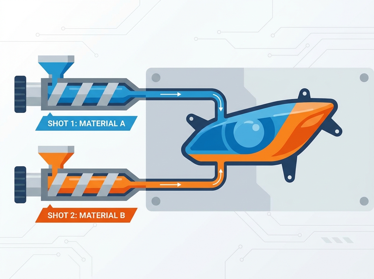
The machine architecture and process flow differ significantly between these two methods. A continuous, single-machine process utilizes two or more injection units working in tandem. The primary substrate remains inside the mold while the machine indexes to the secondary cavity. This keeps the substrate hot, which maximizes chemical adhesion. Traditional overmolding often requires manual or robotic transfer between entirely separate machines. The substrate cools down during this transfer. A cold substrate resists chemical bonding and often requires aggressive mechanical interlocks to stay intact.
Defect rate analysis strongly favors the continuous molding approach. Keeping the primary substrate within a single closed environment mitigates airborne contamination. Dust and debris cannot settle on the bonding surface. Thermal degradation is minimized because the part is not exposed to ambient factory temperatures. Alignment errors between the first and second shots are virtually eliminated. The mold itself dictates the positioning, ensuring superior accuracy and repeatability across millions of cycles.
| Process Characteristic | Two-Shot Molding | Traditional Overmolding |
|---|---|---|
| Machine Requirement | Single multi-barrel press | Two separate standard presses |
| Substrate Temperature | Remains hot (optimal for bonding) | Cools to room temperature |
| Cycle Time | Overlapping, highly efficient | Sequential, longer overall duration |
| Contamination Risk | Near zero (closed environment) | High (exposed during transfer) |
| Tooling Cost | High (complex mechanisms) | Moderate (two standard molds) |
Evaluating chemical adhesion matrices is the first step in multi-material part design. Engineers must cross-reference polymer compatibility charts before finalizing material selection. Bonding rigid PC/ABS with flexible TPU or TPE is common for automotive interior grips and seals. Bonding PMMA with PC is standard practice for optical lenses. Chemical adhesion relies on polymer chain entanglement at the boundary layer. Both materials must reach their respective melt temperatures simultaneously at the interface to fuse properly.
Designing for mechanical interlocking becomes mandatory when chemical bonding is inherently weak. Some polymer combinations simply repel each other. When chemical adhesion poses a long-term delamination risk under thermal cycling, mechanical features save the design. Implement undercuts along the bonding edge. Add through-holes that allow the secondary material to flow through and rivet itself to the primary substrate. Utilize dovetail locking channels to increase the surface area and provide mechanical grip.
Managing differential shrink rates prevents catastrophic part failure. Every polymer shrinks as it cools. If the primary and secondary materials have vastly different thermal expansion coefficients, the part will warp. Calculate these differences early in the design phase. Compensate for varying shrinkage rates by adjusting the wall thickness or modifying the cooling channel layout. Residual stress builds up at the boundary layer if one material cools faster than the other. This stress eventually leads to cracking or delamination in the field.
Establishing the optimal substrate-to-overmold ratio ensures uniform cooling. The secondary shot should generally be thinner than the primary substrate. If the second shot is too thick, its thermal mass will remelt the primary shot. This causes dimensional instability and sink marks. Maintain a consistent wall thickness throughout the secondary geometry to promote even flow dynamics. Abrupt changes in thickness lead to hesitation, short shots, and unpredictable shrinkage.
The primary shot must maintain absolute structural integrity during the secondary injection phase. The secondary material enters the cavity under extreme injection pressure and high melt temperatures. The primary substrate must withstand these forces without deformation, shifting, or remelting. Design the primary geometry with sufficient ribbing and structural support. The steel of the secondary cavity must clamp tightly against the primary substrate to prevent flash. If the primary part shrinks too much before the second injection, the steel will not seal properly, allowing the second material to bleed over the edges.
Gate placement strategies directly impact the success of a Dual-Material Injection Mold. Position the secondary gates carefully to prevent wash-out of the primary shot. If high-pressure secondary material impinges directly onto a thin section of the primary substrate, it will melt and displace the original plastic. Direct the secondary flow along the surface of the primary part rather than perpendicular to it. Use thermal analysis to predict shear heating at the gate. Valve gates are often preferred in multi-shot applications because they provide precise control over the material flow and leave a clean cosmetic finish.
Venting considerations are critical for complex multi-material geometries. Displaced air must escape the cavity rapidly during the secondary injection. Design strategic venting along the parting line and at the end of fill locations. Inadequate venting traps gas inside the cavity. This leads to short shots where the material fails to fill the geometry. Trapped gas also ignites under high pressure, causing diesel-effect burn marks at the material boundary. These burn marks destroy chemical adhesion and ruin the aesthetic finish.
The mechanics of a rotary platen dictate the speed and precision of the molding cycle. This mechanism relies on a 180-degree or 120-degree rotation within a multi-barrel injection molding machine. After the primary shot is injected, the mold opens. The moving half of the mold, carrying the primary substrate, rotates to align with the secondary cavity. The mold closes, and the secondary material is injected. This allows the primary substrate to seamlessly index to the secondary cavity without leaving the machine environment. The rotation is driven by servo motors or hydraulic racks for exact positional accuracy.
Identifying the best use cases for rotary designs ensures optimal return on investment. This mechanism is perfectly suited for high-volume, symmetrical, or multi-cavity production runs. It is the standard approach for a complex Two-Shot Mold for Automotive Parts. Typical applications include interior trim panels, HVAC dials, and multilayer bezels. The rotary platen maximizes output by allowing simultaneous injection. While the secondary material fills the first part, the primary material fills the next part. This overlapping cycle time drastically increases production efficiency.
Machine integration for rotary molds requires careful verification of press specifications. You must confirm the maximum weight capacity of the machine's moving platen. Rotary molds are exceptionally heavy due to the additional steel plates and internal mechanisms. If the mold exceeds the platen weight limit, it will cause premature wear on the machine's tie bars and linear bearings. Additionally, verify the tie-bar spacing to ensure the mold can rotate freely without striking the machine frame.
The core-back approach offers a simpler alternative to rotary platens. This method uses sliding cores to open secondary cavities without rotating the mold. After the primary shot is injected, hydraulic or pneumatic cylinders pull specific steel cores backward. This creates an empty void adjacent to the primary substrate. The second barrel then injects material into this newly created space. The mold never opens during the transition. This approach is ideal for simple geometries like continuous seals, gaskets, and linear edge grips. It reduces tooling costs but limits geometric flexibility.
Evaluating robotic transfer systems requires balancing automation costs against cycle time impacts. In this setup, a 6-axis robotic arm extracts the primary substrate from the first cavity and places it into a secondary cavity within the same machine footprint. This allows for highly complex geometries that cannot be molded using a rotary or core-back design. However, robotic transfer introduces trade-offs. It increases cycle time due to the physical movement of the robot. Orientation accuracy becomes a critical variable. Furthermore, the substrate loses thermal energy during the transfer, which negatively impacts chemical adhesion during the second shot.
Managing the complexities of multi-color optical injections requires absolute precision. Automotive lighting demands flawless integration of different optical polymers. Engineers frequently inject multi-color polycarbonate (PC) or acrylic (PMMA) in a single cycle. A common application involves integrating a clear lens with an opaque black housing. Another involves molding a clear backup lens alongside a red tail light segment. Executing this in a Two-Shot Automotive Headlight Mold eliminates the need for secondary gluing. Gluing optical components often leads to fogging, outgassing, and moisture intrusion over time.
Specifying tool steel and finishing requirements is non-negotiable for optical components. Standard tool steels will not suffice. You must specify high-grade, vacuum-degassed tool steels like Stavax ESR or H13 to prevent surface imperfections. The molding surfaces require SPI A-1 or A-2 diamond polishing standards. This extreme level of polish ensures strict optical compliance and prevents light scattering. Any scratch, pit, or machining mark on the steel will transfer to the plastic lens. This creates light bleed and causes the component to fail photometric testing.
Implementing advanced conformal cooling strategies is mandatory for thick optical components. Automotive lenses often feature varying wall thicknesses to direct light beams accurately. Thick sections take significantly longer to cool than thin sections. Extended cycle times reduce production efficiency. More importantly, uneven cooling causes sink marks and internal voids. Conformal cooling channels follow the exact contour of the lens geometry. This ensures uniform heat extraction across the entire part. Water lines are placed precisely where thermal mass is concentrated, often utilizing 3D-printed metal inserts (DMLS) to achieve complex cooling geometries.
Mitigating residual stress prevents catastrophic field failures. When a thick-walled lens cools unevenly, internal stresses become locked into the polymer chains. This manifests as birefringence, which distorts the light passing through the lens. Over time, residual stress leads to crazing—a network of microscopic cracks on the surface. Prolonged UV exposure and aggressive thermal cycling exacerbate this issue. Uniform cooling, driven by optimized mold flow analysis and conformal cooling channels, is the only way to eliminate residual stress in optical components.
The primary risk associated with multi-material molding is the increased wear and tear on moving mold components. Rotary tables, sliding cores, and lifters operate under immense clamping force and high temperatures. Over hundreds of thousands of cycles, these moving parts experience friction and wear. This wear leads to tolerance drift. When steel components lose their tight tolerances, plastic escapes the cavity. This creates flash along the parting line. Flash on an automotive component requires manual trimming, which defeats the purpose of an automated process.
Mitigating this risk requires strict material specifications and proactive maintenance. Specify high-hardness tool steels for all moving components. Apply specialized wear coatings, such as Titanium Nitride (TiN) or Diamond-Like Carbon (DLC), to sliding surfaces. These coatings reduce friction and prevent galling. Mandate strict predictive maintenance schedules. Molders must inspect, clean, and lubricate the tool at predetermined cycle intervals. Waiting for flash to appear before performing maintenance guarantees production downtime and rejected parts.
A standard preventative maintenance schedule for multi-shot tooling includes:
The financial and technical difficulty of prototyping a Two-Color Injection Mold presents a significant barrier. Traditional single-shot parts are easily prototyped using soft aluminum tooling. Multi-material parts require complex mechanisms that are expensive to replicate in a prototype environment. Building a bridge tool with rotary capabilities often exceeds the prototyping budget. This forces engineering teams to rely heavily on theoretical data before committing to production steel.
Utilizing advanced validation techniques bridges this gap. Mold flow simulation software is the most critical tool in this phase. Engineers use simulation to predict fill patterns, shear rates, and thermal behavior during both injection phases. Simulation identifies potential wash-out zones and trapped gas locations. Supplement this digital validation with multi-material 3D printing. Modern PolyJet printers can simulate different durometers and colors in a single print. This allows for initial fit-and-function testing, ergonomic evaluation, and packaging checks before cutting expensive tool steel.
Analyzing the upfront cost premium is the first step in financial justification. Specialized multi-material tooling generally carries a significant cost increase over standard single-shot molds. The complexity of rotary mechanisms, additional hot runner systems, and precise shut-offs drives this cost. Furthermore, you must partner with molders equipped with multi-barrel machines. These machines are capital-intensive, which often translates to higher hourly press rates. The initial CapEx can be intimidating for procurement teams accustomed to standard molding quotes.
Calculating the long-term OpEx savings reveals the true value of the process. The ROI is generated entirely on the assembly floor. You eliminate direct labor associated with gluing, sonic welding, or manual assembly. You lower scrap rates because the automated process removes human error. You consolidate supply chains by receiving a finished, multi-material component from a single vendor. Zero secondary assembly means zero maintenance on assembly fixtures, ultrasonic welders, or adhesive dispensing robots. For high-volume automotive programs, the OpEx savings quickly eclipse the initial CapEx premium.
Assessing the physical limits of mold cavitation determines long-term scalability. Multi-material molds require significantly more physical space than standard molds. The machine platen size and tie-bar spacing dictate how many cavities can fit inside the press. The footprint of dual injection units also limits machine availability. Engineers must balance the desired cavitation with the physical constraints of the available molding equipment. Pushing the cavitation too high may force the tool into a massive, specialized press that limits production flexibility.
Evaluating design flexibility ensures the tool remains viable throughout the vehicle's lifecycle. Automotive designs change frequently. Minor mid-cycle facelifts alter the geometry of bezels, dials, and lenses. Design the mold to accommodate these changes without requiring a completely new mold base. Utilize interchangeable steel inserts for areas prone to design updates. This modular approach allows you to update the aesthetic features of the part while maintaining the core rotary mechanism and runner system. Future-proofing the tool maximizes the return on the initial capital investment.
To successfully implement a multi-material manufacturing strategy and mitigate tooling risks, execute the following action-oriented steps:
A: A two-shot mold executes both material injections within a single machine cycle using a specialized rotary or core-back mechanism. The primary substrate remains hot, ensuring superior chemical adhesion. Overmolding typically requires transferring a cooled primary part into a completely separate machine for the second injection. This increases cycle time and introduces airborne contamination risks.
A: Yes. The process requires a machine equipped with two or more independent injection barrels. It also requires specialized platen mechanics. You need a servo-driven rotary table or complex hydraulic core-pull systems to index the mold between the first and second injection phases accurately.
A: Adhesion relies on selecting chemically compatible polymers that fuse at the melt interface. If chemical compatibility is low, engineers must design mechanical interlocks into the primary substrate. Features like undercuts, dovetails, or through-holes physically capture the secondary material and prevent delamination.
A: Common defects include wash-out, where the second shot melts and displaces the first shot. Flash at the material boundary occurs due to inadequate shut-offs. Delamination happens from poor chemical adhesion. Short shots result from trapped gas in complex secondary cavities lacking proper venting.
A: Generally, no. Standard single-barrel machines cannot inject two distinct materials simultaneously or sequentially without manual intervention. Some molders retrofit standard machines with bolt-on secondary injection units and auxiliary rotary platens. However, this setup is less efficient and harder to control than a dedicated multi-barrel press.
A: Automotive headlights typically utilize optical-grade Polycarbonate (PC) or Polymethyl Methacrylate (PMMA) for clear lenses. These mold in conjunction with opaque, heat-stabilized PC or PC/ABS blends for the structural housings and bezels. This combination ensures precise optical alignment and withstands high operating temperatures.