- All
- Product Name
- Product Keyword
- Product Model
- Product Summary
- Product Description
- Multi Field Search
Views: 0 Author: Site Editor Publish Time: 2026-10-20 Origin: Site

The transition to electric vehicles shifts the engineering bottleneck from internal combustion efficiency to battery range optimization. Vehicle weight reduction and lowering lifecycle greenhouse gas emissions stand as primary engineering mandates. Replacing legacy metal components with advanced polymers requires overcoming structural, thermal, and NVH challenges. Poor tooling design leads to part warpage, compromised crashworthiness, and unacceptable production scrap rates.
Achieving high-strength, low-weight plastic components relies entirely on precision engineering at the tooling stage. This guide evaluates how strategic Automotive Injection Mold Design dictates the success of metal-to-plastic conversion, ensures dimensional stability, and drives long-term production success.
Electric vehicle efficiency relies heavily on fundamental physics. Every kilogram removed from the vehicle chassis directly correlates to extended battery range. Weight reduction allows engineers to specify smaller, lighter battery packs. This creates a compounding effect on overall vehicle mass. Lower mass reduces the energy consumption required for acceleration. It also decreases the kinetic energy that braking systems must dissipate. Achieving these weight targets requires a massive shift in material selection.
Automakers are moving away from heavy aluminum and stamped steel. They now utilize engineered thermoplastics. Materials like PEEK, glass-filled nylon, and polycarbonates dominate new vehicle architectures. Advanced composite materials offer tensile strengths comparable to traditional metals. However, their specific gravity is significantly lower. Steel has a specific gravity of roughly 7.8. Aluminum sits around 2.7. A 30% glass-filled nylon component drops that number to approximately 1.3. This metal-to-plastic conversion represents a fundamental change in manufacturing strategy. You cannot simply swap materials using legacy component designs. The structural integrity of the vehicle must remain intact.
Sustainability goals further drive this material transition. Lightweighting improves vehicle performance on the road. It also reduces the carbon footprint during the manufacturing process. Processing highly recyclable thermoplastics requires less energy than smelting and stamping metals. Injection molding produces near-net-shape components. This eliminates the extensive machining and material waste associated with metal fabrication. The environmental benefits extend through the entire vehicle lifecycle.
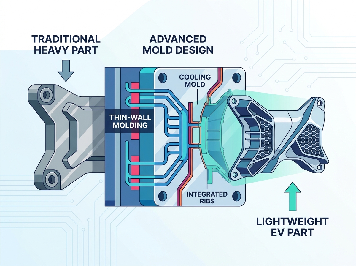
The success of this transition depends entirely on the mold. Lightweighting requires complex mold geometries. Engineers must incorporate heavy ribbing, strategic gussets, and honeycomb structures. These features maintain structural rigidity while minimizing nominal wall thickness. The mold must withstand extreme injection pressures, often exceeding 20,000 PSI. It must also control the cooling rate of complex polymer matrices. Without precision tooling, the benefits of advanced lightweight materials remain unrealized. The mold is the definitive tool for translating polymer science into functional automotive components.
Designing a Lightweight Automotive Parts Mold requires specialized engineering approaches. Standard injection molding techniques often fail when processing high-performance automotive polymers. Engineers must adapt the tool to handle extreme pressures, abrasive fillers, and complex internal geometries. Several core principles dictate the success of these advanced molds.
Thin-wall molding optimization is a primary requirement. Reducing wall thickness directly removes weight from the component. However, injecting high-viscosity polymers into thin cavities requires immense pressure. The mold must feature specialized runner systems to maintain melt temperature. Venting becomes a strict requirement. Trapped air causes short shots or diesel burns in thin-wall sections. Engineers calculate precise vent depths to allow air escape without causing flash. For example, polycarbonate requires vent depths around 0.03mm, while nylon requires tighter vents around 0.015mm to prevent material leakage.
Long-Fiber Thermoplastic (LFT) tooling presents unique challenges. LFT materials offer aerospace-grade strength-to-weight ratios. They maintain passenger safety in crash scenarios. However, the mold must protect the integrity of the long glass or carbon fibers during injection. Specialized gate sizing prevents fiber breakage. High-shear areas within the runner system must be eliminated. If the fibers break during injection, the final component loses its structural advantage.
Conformal cooling integration improves thermal management. Traditional straight-line cooling channels often fail to reach complex geometric features. This results in uneven cooling and severe warpage. Engineers now use Direct Metal Laser Sintering (DMLS) to 3D-print mold inserts. These inserts feature conformal cooling channels that follow the exact contour of the part. This manages thermal distribution perfectly. It reduces cycle times and ensures dimensional stability in complex lightweight components. Water flow must achieve a Reynolds number above 4000 to ensure turbulent flow, maximizing heat transfer away from the plastic.
Gas-assist and foam injection tooling offer alternative lightweighting strategies. These specialized mold designs introduce inert gases or chemical foaming agents during the injection cycle. The gas hollows out thick sections of the part. This reduces overall weight without sacrificing stiffness. The mold must feature precise gas pin placement. It must also maintain perfect cavity pressure to prevent surface defects.
Multi-shot and overmolding capabilities eliminate heavy mechanical fasteners. Molds can combine rigid structural substrates with soft-touch materials in a single cycle. They can also mold integrated elastomeric seals directly onto rigid housings. This reduces the total part count. It eliminates the weight of metal screws, clips, and separate rubber gaskets. The tool must feature precise rotary platens or core-pull mechanisms to execute these multi-material injections flawlessly.
To execute these principles, engineering teams follow a strict sequence during tool development:
The choice of polymer directly dictates the metallurgy and architecture of the Automotive Plastic Injection Mold. You cannot use standard P20 tool steel for advanced composites. The physical properties of the injected material require specific mold adaptations. Abrasive wear resistance, thermal conductivity, and shrinkage control govern tool design.
Structural lightweighting relies heavily on carbon-fiber or glass-fiber reinforced polymers. These materials are highly abrasive. As they flow through the mold, they act like liquid sandpaper. Tool steel selection is critical. Engineers must specify high-hardness materials like H13 or S7 tool steel, typically hardened to 50-54 HRC. For extreme volume production, specialized powder metallurgy steels like CPM 9V provide maximum wear resistance. Gate areas and runner intersections experience the highest shear. These zones often require replaceable inserts coated with titanium nitride or diamond-like carbon.
Thermal conductivity must balance with wear resistance. High-hardness steels typically exhibit poor heat transfer. Rapid heat dissipation is necessary to maintain fast cycle times. It also prevents localized hot spots that cause part degradation. Engineers solve this by integrating beryllium copper alloys in specific mold areas. Beryllium copper pulls heat away from the plastic rapidly. It is often used in deep core pins or complex rib sections where traditional water lines cannot fit.
Shrinkage and tolerance control require precise mathematical calculation during the cavity design phase. Polymers shrink as they cool from a molten state to a solid. Semi-crystalline polymers, like nylon or PBT, exhibit high and anisotropic shrink rates. They shrink differently in the direction of flow compared to the transverse direction. Amorphous polymers, like polycarbonate, shrink more uniformly. Engineers must calculate these exact shrink rates. They apply these calculations to the mold cavity dimensions. This ensures the final molded part meets strict automotive tolerances.
| Polymer Type | Common Automotive Application | Mold Steel Recommendation | Typical Shrinkage Rate (in/in) | Tooling Challenge |
|---|---|---|---|---|
| Glass-Filled Nylon (PA66-GF30) | Under-hood brackets, structural frames | H13 or Powder Metallurgy (HRC 50-54) | 0.003 - 0.006 (Highly Anisotropic) | Extreme abrasive wear at gate locations. |
| Polycarbonate / ABS Blend | Interior trim, center consoles | P20 or NAK80 (HRC 30-40) | 0.005 - 0.007 (Uniform) | Maintaining Class-A surface finish; preventing flow marks. |
| Polypropylene (Talc Filled) | Bumper fascias, interior panels | P20 (HRC 30-35) | 0.010 - 0.020 | Managing long flow lengths and preventing warpage. |
| PEEK (Carbon Fiber Reinforced) | E-motor components, thrust washers | Premium Powder Metallurgy (HRC 58+) | 0.004 - 0.008 | High melt temperatures require specialized mold heating systems. |
| Polyphenylene Sulfide (PPS) | Cooling system manifolds, inverter housings | H13 with Titanium Nitride Coating | 0.002 - 0.005 | Requires hot oil circulation to achieve proper crystallization. |
An EV Plastic Parts Mold is not a universal tool. The engineering requirements shift drastically depending on where the component lives on the vehicle. Interior aesthetics demand different tooling strategies than under-hood structural components. Understanding these application-specific requirements ensures the mold delivers the necessary performance.
The primary criteria for an Automotive Interior Trim Mold are aesthetics, NVH reduction, and passenger safety. Components like dashboards, door panels, and center consoles sit directly in the driver's line of sight. They require flawless Class-A surface finishes.
Design focus centers on visual perfection. Engineers must incorporate complex parting lines that hide seamlessly in the final assembly. Advanced graining and texturing are etched directly into the mold cavity. This replicates the look of leather or premium fabrics. Draft angles must be calculated precisely based on texture depth, typically requiring 1.5 degrees of draft per 0.001 inches of texture depth to prevent scuffing during ejection. Optimizing gate locations is essential. The mold must eliminate visible flow marks, weld lines, and gate vestige on any visible surface. Additionally, interior molds often incorporate precise mounting bosses for NVH dampening materials. This prevents rattles and squeaks in the silent cabin of an electric vehicle.
An Automotive Exterior Trim Mold focuses on aerodynamics, weatherability, and impact resistance. Bumpers, grilles, and aero-wheel covers dictate the aerodynamic efficiency of the EV. They also serve as the first line of defense in low-speed collisions.
These components require engineering large-tonnage molds. Bumper fascias are massive parts. They require injection molding machines with thousands of tons of clamping force. The mold design must address the challenges of long flow lengths. The plastic must travel significant distances before freezing off. Engineers use sequential valve gating systems. This controls the flow front precisely. It ensures dimensional stability across large surface areas and prevents sink marks over structural mounting ribs. Hot runner systems must maintain uniform temperature profiles across manifolds that span several feet.
E-powertrain components operate in harsh environments. The criteria focus on chemical resistance, extreme thermal cycling, and dielectric properties. Inverter housings, cooling system manifolds, and e-motor components protect the high-voltage architecture of the vehicle.
Tooling for these parts requires absolute precision. The mold must facilitate the flow of highly engineered, flame-retardant polymers like PPS or PEEK. Precision gating and venting are mandatory. Trapped gas or poor flow causes stress fractures. These fractures lead to catastrophic failure under high thermal loads. Furthermore, these molds often require tight tolerances for O-ring grooves. This ensures hermetic sealing, protecting sensitive electronics from moisture and automotive fluids. Mold heating systems, such as hot oil circulation, are often required to keep the tool surface hot enough to achieve proper crystallization of high-temperature resins.
Battery enclosures and structural brackets represent the ultimate lightweighting challenge. The criteria focus on thermal management, flame retardancy, and crashworthiness. These components house the most volatile system in the EV: the battery pack.
Tooling design emphasizes heavy ribbing. This provides maximum stiffness with minimum wall thickness. Insert molding is heavily utilized. The mold holds threaded metal inserts in place while the plastic injects around them. This provides robust mounting points for the heavy battery modules. Strict knit-line management is the most critical factor. When two flow fronts meet in the mold, they form a knit line. This is inherently the weakest point of the plastic part. Engineers must design the mold to force knit lines into non-load-bearing areas. This prevents structural failure during a crash event.
Procuring tooling requires balancing production volume expectations against tool longevity. Engineering teams must evaluate several factors before cutting steel.
Tooling classification dictates the build strategy. High-volume EV platforms require SPI Class 101 molds. These tools are built for millions of cycles. They utilize premium hardened steels, complex cooling circuits, and guided ejection systems. Lower-volume niche vehicles or prototype runs may utilize Class 103 molds. These use pre-hardened steels like P20 and simpler architectures. The engineering team must align the mold classification with the expected lifecycle of the vehicle platform.
Cavitation strategy presents another engineering trade-off. Single-cavity molds offer easier tolerance control for large, complex parts. The flow dynamics are simpler to manage. Multi-cavity molds increase production output per cycle. However, they introduce significant complexity. The runner system must be perfectly balanced to ensure all cavities fill simultaneously. Cavity imbalance leads to inconsistent part weights, flash on over-packed cavities, and short shots on under-packed cavities.
Sourcing location impacts project execution. Domestic tooling offers rapid communication, easier on-site tryout attendance, and tighter control over intellectual property. Offshore tooling often provides different lead time structures. However, engineers must account for the logistics of tool shipping, potential communication delays during the DFM phase, and the complexities of executing engineering changes across different time zones.
Transitioning from metal to plastic introduces specific manufacturing risks. Tooling defects compromise the safety and functionality of the vehicle. Identifying these risks during the mold design phase prevents catastrophic failures in production. Mitigation relies on rigorous engineering analysis and precise tool execution.
Warpage and dimensional instability represent a primary risk. When a plastic part cools unevenly, residual stress builds within the polymer matrix. Upon ejection from the mold, the part twists or bows. This renders it unusable for assembly. Mitigation requires mandatory Moldflow and mold-filling simulation during the Design for Manufacturability (DFM) phase. Engineers simulate the cooling process virtually. They adjust cooling channel layouts and water flow rates before cutting any steel. This ensures uniform temperature distribution across the entire cavity.
Weak knit lines in structural parts pose a severe safety risk. As molten plastic flows around a core pin or through a complex geometry, the flow front splits. When the fronts reunite, they create a knit line. In fiber-reinforced plastics, the fibers do not cross this line. This creates a localized weak point. If a knit line occurs in a high-stress area, the part will fail during a crash. Mitigation involves strategic gating. Engineers use sequential valve gating to control exactly where the flow fronts meet. They intentionally push the knit lines into thick, low-stress regions of the component.
Sink marks on visible surfaces ruin the aesthetic quality of interior and exterior trims. Sink marks occur when thick underlying features, like mounting ribs or bosses, cool slower than the adjacent thin wall. The shrinking material pulls the surface inward, creating a visible dimple. Mitigation requires strict adherence to rib-to-wall thickness ratios. The base of a rib should typically not exceed 60% of the nominal wall thickness. This geometric rule must be engineered directly into the mold cavity design. It prevents thermal mass imbalances and ensures a flawless Class-A surface.
Automotive injection mold design serves as the foundational step in EV lightweighting. Poor tooling architecture cannot be corrected by advanced processing parameters or premium resin selection. The structural integrity, aesthetic quality, and dimensional stability of the final component depend entirely on the precision of the mold. To ensure successful metal-to-plastic conversion, engineering teams must take decisive action during the development phase.
A: Conformal cooling channels follow the exact geometric contours of complex parts. This provides uniform heat dissipation, which prevents warpage and significantly reduces cycle times compared to traditional straight-line cooling methods.
A: Injection molding allows engineers to replace heavy metal components with advanced, high-strength polymers. By designing molds with complex ribbing and thin walls, parts maintain structural rigidity while shedding significant mass.
A: Knit lines form when two molten plastic flow fronts meet inside the mold. In fiber-reinforced materials, fibers do not bridge this gap, creating a localized weak point that can fail under stress.
A: Glass and carbon fibers are highly abrasive. Injecting them at high pressure acts like liquid sandpaper. High-hardness tool steels, like H13 or powder metallurgy grades, are required to prevent rapid mold wear.
A: Engineers prevent sink marks by strictly controlling the rib-to-wall thickness ratio during the mold design phase. Keeping underlying ribs to roughly 60% of the nominal wall thickness prevents uneven cooling and surface dimpling.
A: Sequential valve gating allows precise control over multiple injection points. It manages the flow front of the molten plastic, helping to eliminate visible flow marks and push weak knit lines into non-critical areas.