- All
- Product Name
- Product Keyword
- Product Model
- Product Summary
- Product Description
- Multi Field Search
Views: 0 Author: Site Editor Publish Time: 2026-10-20 Origin: Site

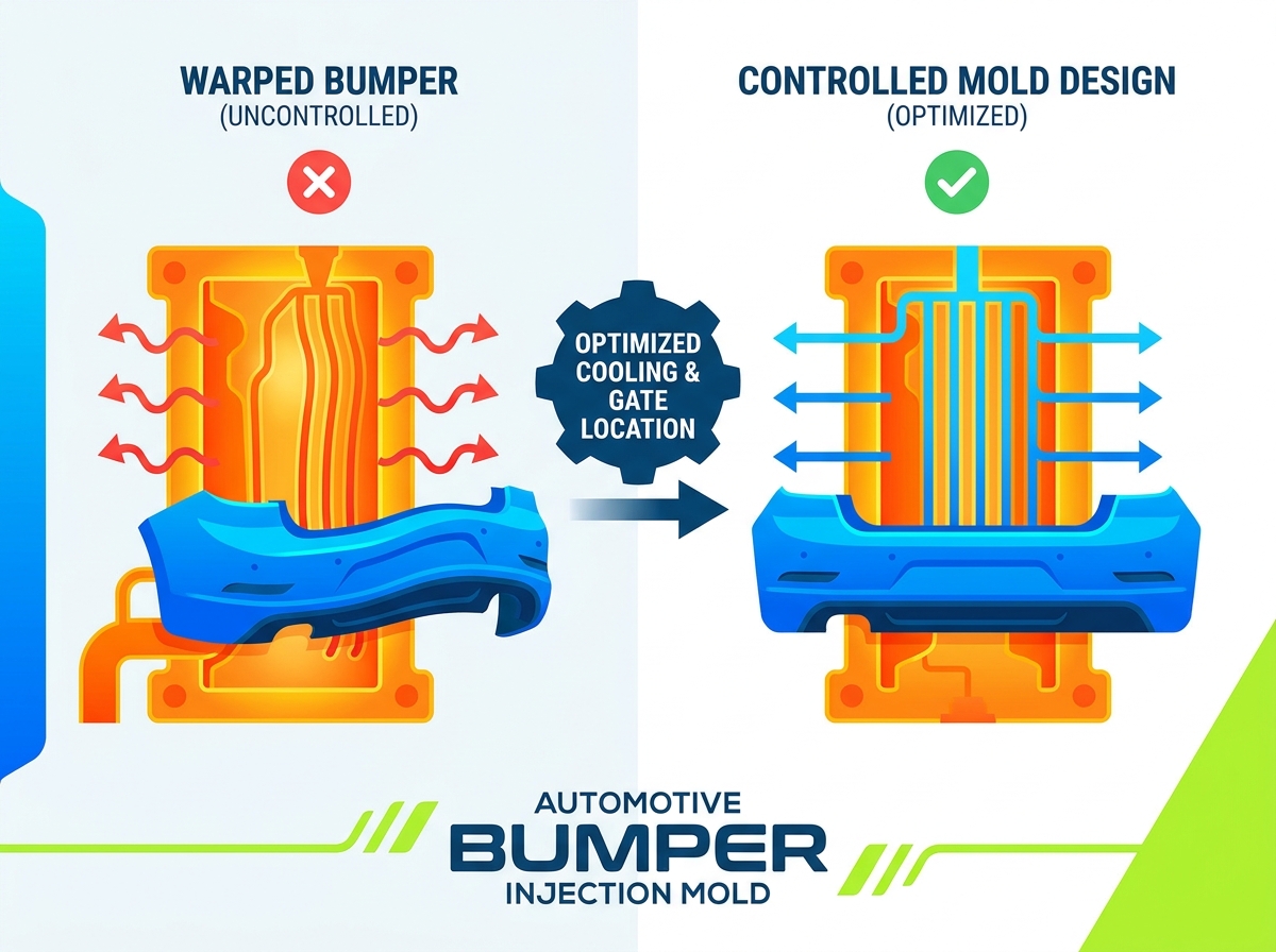
Dimensional instability in large-format automotive components creates severe operational impacts. Scrap rates climb, assembly lines face bottlenecks, and vehicle launch timelines slip when fascias fall out of tolerance. The core problem lies in the inherent conflict between the complex, sweeping geometries required for modern aerodynamic bumpers and the physics of plastic shrinkage. If you do not aggressively manage this during the tooling engineering phase, it predictably leads to warpage, gap-and-flush failures, and assembly rejection.
Mitigating warpage is not a downstream processing parameter issue you can solve at the press. It is a strict structural engineering requirement. You must engineer dimensional stability directly into the tooling through advanced cooling, gating, ejection strategies, and absolute mold rigidity.
Defining acceptable gap-and-flush tolerances establishes the baseline for success in fascia manufacturing. Modern automotive standards often require tolerances as tight as +/- 0.5mm across mating surfaces like fenders and headlamps. Achieving this requires controlling the primary causes of warpage: differential shrinkage, orientation-induced stress, and thermal imbalances. When a massive polymer melt cools unevenly, the resulting internal stresses force the part to deform upon ejection. An engineered Automotive Exterior Trim Mold must counteract these forces through precise thermal and structural management.
Common bumper materials interact with mold surfaces in distinctly different ways. Standard Thermoplastic Olefins (TPOs) exhibit relatively isotropic shrinkage, meaning the material shrinks uniformly in all directions. This makes warpage prediction straightforward. Conversely, glass-fiber reinforced polypropylene blends exhibit highly anisotropic shrinkage. As the polymer flows through the cavity, the glass fibers align with the flow direction. Shrinkage perpendicular to the fiber alignment is significantly higher than shrinkage parallel to it. This flow-induced residual stress dictates that gating strategies must align the melt flow with the structural geometry of the bumper to prevent twisting.
| Material Type | Shrinkage Behavior | Warpage Risk Factor | Tooling Mitigation Strategy |
|---|---|---|---|
| Standard TPO | Isotropic (Uniform) | Moderate | Standard conformal cooling, symmetrical gating |
| Glass-Filled PP | Anisotropic (Directional) | High | Flow-aligned gating, aggressive core cooling |
| PC/PBT Blends | Low Shrinkage, High Stress | High | High mold temperatures, slow injection speeds |
Designing for structural ribs, mounting bosses, and varying wall thicknesses introduces localized volumetric shrinkage. Thick sections take longer to cool and require higher packing pressures to compensate for polymer contraction. Uneven packing across a large fascia leads to localized volumetric shrinkage. This manifests as sink marks on the Class-A surface or localized warping around attachment points. Engineers must utilize strict coring guidelines, keeping rib thickness at 50% to 60% of the nominal wall thickness, to minimize thermal mass and prevent differential cooling rates.
Controlling deformation requires a multi-disciplinary engineering approach. Tooling engineers must integrate advanced thermal management, precise flow control, and absolute mechanical rigidity to ensure dimensional integrity.
Thermal management is the primary defense against warpage. Conformal cooling, achieved through 3D metal printing or vacuum brazing, allows water channels to follow the exact contours of deep cores and complex fascia geometries. Traditional straight-drilled water lines cannot reach these deep areas, leading to hot spots. Baffle and bubbler placements are engineered to ensure uniform temperature distribution across the massive surface area of the tool.
Managing the Delta-T (temperature differential) between the cavity and core halves dictates part stability. If the core runs hotter than the cavity, the plastic will shrink more on the core side, causing the bumper to bow inward. You must design the cooling layout to maintain a Delta-T of less than 2°C across the entire molding surface. Furthermore, the cooling channels must be sized to guarantee a Reynolds number above 4,000. This ensures turbulent water flow, which maximizes heat transfer efficiency and prevents laminar boundary layers from insulating the tool steel.
Melt delivery directly impacts residual stress. Sequential valve gating (SVG) is standard for large fascias. Evaluating pneumatic versus servo-driven valve gates reveals that servo systems offer superior pin velocity control. This manages the melt front advancement, optimizes packing pressure, and eliminates high-stress weld lines. In a Plastic Bumper Injection Mold, symmetrical gate placement ensures balanced flow, preventing the core from shifting under uneven injection pressure.
Managing shear stress and pressure drops across long flow lengths requires precise manifold sizing. Engineers optimize gate freeze-off timing by controlling the temperature at the gate tip. This ensures that thick sections, such as mounting brackets, remain fully packed during the holding phase, preventing volumetric shrinkage and subsequent deformation.
Injection pressures for large bumpers often exceed 3,000 tons of clamping force. This requires massive mold base support. Robust support pillars and interlocking mechanisms, including straight and tapered locks, are integrated into the parting line. These interlocks align the cavity and core halves with zero clearance, withstanding immense lateral forces.
Preventing micro-deflection of the core ensures uniform wall thickness. Even a 0.1mm core shift alters the wall thickness, changing the cooling rate and creating a mechanical imbalance that guarantees warpage. High-grade forged steel and thick backing plates eliminate platen deflection and maintain absolute rigidity.
Demolding a large fascia introduces significant mechanical stress. Synchronized ejection systems, utilizing stripper plates, angled pins, and hydraulic cylinders, distribute the ejection force evenly across the part. Localized stress from standard ejector pins will push through the soft, hot plastic, causing permanent deformation.
Large, deep-draw bumper fascias create a vacuum effect against the core during ejection. Strategically placed air poppets break this vacuum before the mechanical ejection sequence begins. Additionally, engineers must calculate proper draft angles for heavily textured exterior surfaces. A standard rule requires 1 to 1.5 degrees of draft for every 0.025mm of texture depth. This minimizes ejection drag and prevents demolding deformation.
Front and rear fascias present entirely different engineering challenges due to their distinct structural geometries and functional requirements.
Front bumpers feature aerodynamic, heavily vented designs to accommodate grilles, fog lights, and cooling intakes. These features require complex shut-offs and multiple flow fronts. Rear bumpers typically feature deep-draw, wrap-around geometries with large, uninterrupted surface areas. The lack of venting in a Rear Bumper Mold simplifies the flow front but complicates the cooling and ejection phases due to the massive thermal mass and deep corners.
| Feature | Front Bumper Mold | Rear Bumper Mold |
|---|---|---|
| Flow Dynamics | Complex, multiple weld lines due to grilles | Smooth, long flow lengths requiring high pressure |
| Cooling Focus | Around shut-offs and complex side-actions | Deep wrap-around corners (horseshoe effect) |
| Tooling Complexity | High (multiple slides, lifters, side-actions) | Moderate to High (massive lifters for deep undercuts) |
The long, wrap-around corners of rear bumpers tend to warp inward post-ejection, a phenomenon known as the horseshoe effect. As the inner surface of the corner cools, it contracts and pulls the ends of the bumper toward the center. Counteracting this requires aggressive conformal cooling on the inner core radii and slightly warmer temperatures on the outer cavity radii to balance the thermal contraction vectors.
The presence of grilles, fog light bezels, and sensor housings in front bumpers alters flow dynamics. The polymer melt must navigate around these steel shut-offs, creating flow hesitation and stress concentrations. Weld lines form where the flow fronts recombine. Rear bumpers, with their solid expanses, allow for smoother flow dynamics but require higher injection pressures to push the material across long, uninterrupted distances without freezing off prematurely.
Bumper orientation and undercut requirements dictate tooling complexity. Front bumpers often require complex slide mechanisms, lifters, and side-actions to mold sensor brackets and intricate grille attachments. These moving components complicate cooling line routing, as water must be channeled through moving steel. Rear bumpers may require fewer slides but demand massive lifters to clear the deep undercuts of the wrap-around corners, requiring robust hydraulic actuation to prevent mechanical binding.
Procuring a large-format mold requires auditing a vendor's technical capabilities to ensure they can deliver a warp-free, production-ready asset.
A vendor's proficiency in Moldflow analysis is the first indicator of competence. Look for transparent reporting on predicted volumetric shrinkage, fiber orientation analysis, and cooling efficiency. The DFM report must detail how the gating strategy mitigates weld lines and how the cooling layout addresses predicted hot spots. If the vendor relies on generic flow simulations rather than material-specific warp analysis, the risk of dimensional failure increases significantly.
Strict adherence to automotive standards is non-negotiable. The manufacturer must hold IATF 16949 certification and demonstrate a proven history of Tier-1 automotive deliveries. Their engineering team must understand the Production Part Approval Process (PPAP) and integrate statistical process control into their tryout procedures. This ensures the Automotive Bumper Mold will perform consistently under mass production conditions.
The longevity and stability of the mold depend on the steel grade and machining precision. High-grade forged tooling steel, such as 1.2738 or P20 for the main blocks, provides the necessary toughness. High-wear areas and interlocks require harder alloys like H13 hardened to 48-52 HRC. Furthermore, 5-axis CNC machining precision ensures that parting lines mate perfectly and shut-offs seal without flashing, maintaining the structural integrity of the tool under high tonnage.
Strict criteria must be established for mold tryouts. T0 and T1 sampling should include comprehensive process window documentation. The vendor must provide CMM (Coordinate Measuring Machine) inspection reports of the molded parts, comparing the physical dimensions directly to the CAD data. Core shift measurements and thermal imaging of the mold during cycling provide empirical proof that the cooling and rigidity engineering is functioning as designed.
Navigating the commercial realities of procuring large automotive molds requires balancing upfront investment with long-term production stability.
Underinvesting in a complex cooling system or opting for pneumatic rather than servo-driven hot runners creates immediate risks. The initial savings are rapidly eclipsed by exponentially higher costs in scrapped parts, assembly line rework, and the need for secondary fixturing. A thermally balanced mold with precise flow control guarantees a wider process window, drastically reducing the scrap rate during mass production.
Balancing cycle time with dimensional stability requires compromise. Pushing for sub-60-second cycle times demands aggressive cooling. If the mold lacks conformal cooling, forcing a fast cycle time will eject the part before it is structurally rigid, guaranteeing demolding warpage. Investing in advanced cooling architecture allows for faster cycle times without compromising the dimensional integrity of the fascia.
Operational longevity depends on the ease of maintenance. Large molds require regular servicing. The design must facilitate easy access to hot runner nozzles, allow for the rapid replacement of wear plates on slides, and provide accessible ports for flushing conformal cooling channels. A mold designed for easy maintenance minimizes production downtime and ensures consistent part quality over hundreds of thousands of cycles.
Transitioning from mold design to mass production introduces variables that can compromise even the best engineering.
A primary implementation risk is running the tool in an injection molding machine that cannot support its structural requirements. If the press tonnage is inadequate, the injection pressure will blow the mold open, causing flashing and altered packing pressures. Furthermore, platen deflection on older or undersized presses will transfer mechanical stress into the mold base, causing core shift and uneven wall thickness.
While superior mold design minimizes warpage, the reality of large polymer components often requires secondary intervention. Large automotive bumper molds frequently require engineered cooling fixtures, known as shrink fixtures, immediately post-ejection. The fascia is clamped into the fixture to hold its exact CAD dimensions during the polymer's final crystallization phase. This guarantees final tolerances and prevents ambient cooling variations from inducing late-stage warpage in a Bumper Injection Mold.
Mitigating these risks requires collaborative engineering. The mold maker, the resin supplier, and the Tier-1 molder must align during the initial DFM phase. The mold design must be tailored to the exact specifications of the intended injection press, including tie-bar spacing, platen layout, and available hydraulic circuits. This alignment ensures the tooling design matches the actual production environment realities.
To ensure a successful Automotive Bumper Injection Mold project, execute the following steps immediately:
A: The most common cause is uneven cooling and differential shrinkage across the large surface area of the fascia. This is often exacerbated by uneven wall thickness caused by core shift under high injection pressures, leading to localized thermal imbalances and internal stress.
A: Sequential valve gating provides precise control over melt front advancement. By opening gates in a timed sequence, it optimizes localized packing pressure, prevents flow hesitation, and eliminates high-stress weld lines, resulting in a structurally uniform part.
A: Rear bumpers feature deep, complex wrap-around corners. Traditional straight-drilled water lines cannot reach these areas effectively. Conformal cooling extracts heat uniformly from these deep geometries, preventing the thermal contraction that causes the corners to warp inward (the horseshoe effect).
A: Standard TPOs exhibit isotropic shrinkage, shrinking evenly in all directions. Glass-filled materials exhibit anisotropic shrinkage, where the material shrinks differently parallel versus perpendicular to the flow direction. This requires entirely different gating strategies to align flow vectors and minimize twisting.
A: Pre-hardened forged steels like 1.2738 or P20 are standard for the main cavity and core blocks due to their toughness and stability. Harder alloys, such as H13, are utilized for high-wear areas, lifters, and interlocks to prevent mechanical deflection.
A: Evaluate their historical Moldflow accuracy, specifically their warp and cooling analyses. Review their cooling channel design standards, mold rigidity calculations, and demand transparency in their CMM validation and tryout processes for previous large-tonnage projects.