- All
- Product Name
- Product Keyword
- Product Model
- Product Summary
- Product Description
- Multi Field Search
Views: 0 Author: Site Editor Publish Time: 2026-11-06 Origin: Site

High financial and operational stakes define large automotive panel manufacturing. Tooling errors on Class-A surfaces consistently lead to unacceptable scrap rates and delay vehicle launch timelines. Managing massive surface areas presents inherent physical challenges on the production floor. Engineers must control dimensional stability across expansive geometries like dashboards, door panels, and center consoles. Warpage and cosmetic defects easily compromise the final assembly if ignored during the initial engineering phase.
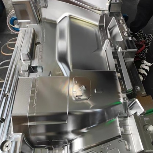
Successful production demands a rigorous, data-backed approach. You cannot rely on trial and error when machining massive steel blocks. Advanced simulation must drive every tooling decision before cutting metal. Selecting a highly capable partner ensures these digital models translate into physical reality. A precision-engineered automotive interior mold forms the foundation of a profitable production run. Specialized gating, thermal management, and strict dimensional controls guarantee zero-defect components.
Interior components demand flawless visual and tactile standards. Consumers interact directly with these surfaces daily, meaning any visible imperfection degrades the perceived quality of the entire vehicle. We map common cosmetic failures directly to specific mold design flaws. Flow marks often indicate inadequate melt temperature control or restrictive gate sizing. Tiger stripes point to unstable flow fronts during injection, usually caused by excessive injection speeds. Sink marks reveal poor packing pressure or improper rib-to-wall thickness ratios on the B-side of the part.
Establishing strict acceptance criteria is mandatory for large panels. Surface finish consistency must remain uniform across expanses exceeding one meter. You cannot tolerate gloss variations on a continuous dashboard panel. Tooling engineers mitigate these defects by optimizing gate locations and runner dimensions. They ensure the plastic melt fills the cavity smoothly and uniformly without hesitation. Proper venting also plays a massive role in maintaining surface integrity by preventing gas traps that cause dull spots.
Maintaining tight tolerances becomes exponentially harder as part size increases. Parts exceeding 1,000mm in length amplify minor shrinkage variations into major assembly failures. A 0.5% shrinkage rate on a 1,200mm door panel equals a 6mm dimensional shift. You must evaluate the impact of resin shrinkage during the cooling phase. Environmental factors like ambient humidity and factory temperature also affect final dimensions on the shop floor.
Baseline metrics for structural integrity dictate assembly fitment. Gap and flush requirements leave zero room for error on the assembly line. If a center console warps by 2mm, it will not align with the mating dashboard components, causing squeaks and rattles. Engineers use reverse deformation strategies to counteract predicted warpage. They cut the steel slightly out of tolerance in the opposite direction of the expected warp. This ensures the final molded part cools into the perfect nominal shape.
Different interior resins require distinct tooling adaptations. Polycarbonate/Acrylonitrile Butadiene Styrene (PC/ABS) blends offer high impact resistance but require high mold temperatures. Thermoplastic Olefins (TPO) provide excellent flexibility and weatherability but are prone to scuffing during ejection. Polypropylene (PP) serves as a cost-effective structural base with high shrinkage rates. Each material exhibits unique flow characteristics that dictate tool design.
Material viscosity dictates runner sizing and gate types. High-viscosity resins require larger runners to prevent excessive shear stress and material degradation. Thermal degradation thresholds influence cooling channel proximity. Heat-sensitive materials need aggressive cooling near the gate to prevent burn marks. You must align the tool design with the specific thermodynamic properties of the chosen polymer.
| Resin Type | Typical Shrinkage Rate | Mold Temperature Requirement | Primary Interior Application |
|---|---|---|---|
| PC/ABS | 0.5% - 0.7% | 60°C - 90°C | Instrument Panels, Center Consoles |
| TPO | 0.8% - 1.2% | 30°C - 50°C | Door Panels, Soft-Touch Skins |
| PP (Glass Filled) | 0.2% - 0.4% | 40°C - 80°C | Structural Carriers, Hidden Brackets |
Filling massive surface areas requires precise melt front control. Sequential valve gating (SVG) dominates large panel production. SVG utilizes hydraulic or pneumatic pins to open and close gates in a specific sequence. This controls the melt front advancement precisely and effectively eliminates weld lines on visible Class-A surfaces. You can pack out large areas uniformly without over-pressurizing the cavity, which prevents flash and reduces clamp tonnage requirements.
Hot runner system selection determines pressure drop balance. A large automotive trim injection mold often utilizes multi-cavity or single large-cavity configurations with up to 10 drops. The manifold must distribute the melt evenly to all drop locations. Trade-offs exist between gate placement, shear stress, and cosmetic outcomes. Placing a gate in a highly visible area requires complex post-molding finishing. Hiding the gate on a non-visible edge might increase the flow length, risking short shots or excessive pressure drops.
Injecting plastic into a massive cavity displaces a huge volume of air. This air must escape rapidly through machined vents. If trapped, it compresses and ignites under high pressure. This phenomenon is known as the diesel effect. It causes severe burn marks on the part and physically pits the tool steel. Strategic venting networks prevent this catastrophic failure.
Engineers design perimeter vents and ejector pin vents with specific depths based on the resin. PP might require 0.02mm vent depths, while PC/ABS can tolerate 0.04mm without flashing. Vacuum venting systems actively pull air from the cavity milliseconds before injection begins. Porous steel inserts offer another solution for deep pockets where traditional vents cannot fit. These inserts allow air to pass through while containing the molten plastic. Proper evacuation eliminates short shots and ensures complete feature replication.
Traditional straight-line cooling channels struggle with complex geometries. They cannot follow the sweeping curves of a modern dashboard or door card. This limitation causes uneven cooling across the tool surface. Hot spots lead to differential shrinkage, extended cycle times, and severe warpage. Advanced thermal management solves this issue by bringing the cooling medium closer to the plastic.
Conformal cooling channels follow the exact contour of the part surface. They maintain a uniform distance from the plastic melt, achieving uniform temperature distribution across the entire panel. It significantly reduces cycle times and minimizes differential shrinkage. Additive manufacturing enables the creation of these complex cooling inserts. The return on investment for 3D-printed inserts proves highly favorable in high-volume production runs by shaving seconds off every cycle.
Modern interiors demand soft-touch surfaces and lightweight structures. Two-shot (2K) molding integrates rigid substrates and soft elastomers in a single cycle. This requires complex tooling architectures. Rotary platens or core-back mechanisms allow the press to inject the second material directly over the first. This eliminates secondary assembly operations and ensures a permanent chemical bond between the two resins.
Chemical foaming and microcellular injection molding reduce part weight. These processes introduce a supercritical fluid into the polymer melt inside the barrel. The fluid expands inside the cavity, creating a microcellular core within the plastic wall. This technique eliminates sink marks on thick-walled ribs and bosses. The tool must maintain strict cavity pressure to control the foaming reaction accurately and prevent surface splay.
Demolding a massive, pliable panel requires careful force distribution. Standard ejector pins often puncture or scuff the warm plastic, especially on soft TPO materials. You must design ejection mechanisms that distribute force evenly across the entire surface area. Stripper plates provide continuous support along the part perimeter, pushing the part off the core without localized stress.
Angled pins and lifters release complex undercuts safely. Synchronized hydraulic ejection ensures all mechanisms move simultaneously. This prevents the part from twisting or binding during removal. Stress whitening occurs when the plastic stretches beyond its yield point during ejection. A well-designed ejection system utilizes larger pin diameters and guided ejection plates to eliminate this cosmetic defect completely.
Cutting steel without simulation guarantees failure on large panels. Automotive mold flow analysis dictates venting design and gate locations digitally. Software simulates the exact flow of molten plastic inside the cavity. It highlights where separate flow fronts converge. These convergence points form weld lines, which present both cosmetic and structural risks.
Engineers analyze melt flow behavior to ensure structural integrity at these knit lines. Weak weld lines around speaker grilles or HVAC vents cause parts to fracture during assembly or deployment of airbags. Simulation allows you to move gate locations or adjust wall thicknesses to push weld lines into non-critical, hidden areas. It also identifies potential air traps, guiding the placement of vacuum vents and porous inserts before the CNC machines start cutting.
Predictive models apply reverse deformation to the mold cavity. This process is called windage. The software calculates exactly how the part will warp after cooling based on fiber orientation and volumetric shrinkage. Engineers then distort the CAD model of the mold in the opposite direction. When the physical part warps, it settles into the correct nominal dimensions required by the assembly gauge.
Simulation evaluates the interplay between packing pressure, cooling rates, and final part geometry. High packing pressure reduces shrinkage but increases internal stress, leading to long-term field failures. Fast cooling rates decrease cycle time but exacerbate warpage. Translating this simulation data into actionable tooling adjustments guarantees first-time-right T0 tryouts. It eliminates the need for expensive, time-consuming weld-and-re-cut loops on the physical tool.
Selecting the right steel dictates the lifespan of the tool and the quality of the molded parts. You must balance upfront material costs against long-term durability. Pre-hardened steels like P20 or NAK80 suit medium-volume production. They machine easily and offer decent polishability. However, they wear out quickly under high-volume stress or when running glass-filled resins.
Fully hardened steels like H13 or S136 dominate high-volume applications. They withstand abrasive resins and high injection pressures. These grades offer superior thermal conductivity and exceptional polishability. A flawless Class-A finish requires high-grade, inclusion-free steel. The table below outlines common choices for an automotive interior exterior trim mold.
| Steel Grade | Hardness (HRC) | Primary Application | Polishability | Wear Resistance |
|---|---|---|---|---|
| P20 | 28 - 32 | Low to Medium Volume, Large Cores | Good | Moderate |
| NAK80 | 38 - 42 | Medium Volume, High Gloss Areas | Excellent | Good |
| H13 | 48 - 52 | High Volume, Abrasive Resins | Very Good | High |
| S136 | 48 - 52 | High Volume, Corrosive Resins | Exceptional | Very High |
Interior panels rarely feature flat, glossy surfaces. They require complex textures to mimic leather, carbon fiber, or geometric patterns. Industry-standard textures dictate specific draft angle requirements on the cavity walls. A deeper texture requires a larger draft angle to prevent drag marks during ejection. The general rule requires 1 to 1.5 degrees of draft per 0.025mm of texture depth.
Chemical etching provides traditional leather grains through a multi-step acid process. Laser texturing allows for complex, multi-gloss geometric patterns. Laser technology maps the texture directly onto the 3D contour of the tool, eliminating stretching or distortion in deep corners. Texturing impacts mold maintenance heavily. Deep grains trap release agents and outgassing residue, requiring frequent ultrasonic cleaning to maintain part quality.
Large molds represent massive capital investments. They must run continuously with minimal downtime for maintenance. Engineering interchangeable inserts for high-wear areas extends tool life significantly. If a gate insert wears out from shear friction, you replace the small insert rather than re-machining the entire 5-ton cavity block.
Complex moving mechanisms require robust engineering. Sliders and lifters handle thousands of cycles daily under immense clamping force. Utilizing self-lubricating wear plates reduces friction and prevents galling between sliding steel components. Hardened steel components in these dynamic areas prevent premature failure. Proper maintenance channels and accessible grease points keep the tool running smoothly on the production floor without requiring removal from the press.
Large panels require massive injection presses, often exceeding 1,500 tons of clamping force. The mold itself can weigh over 20 tons. You must verify the manufacturer's machining capabilities firsthand. They need 5-axis CNC machines with travel envelopes large enough to cut massive steel blocks in a single setup. Multiple setups introduce tolerance stacking errors that ruin parting line shut-offs.
EDM (Electrical Discharge Machining) equipment must also accommodate these large blocks for burning deep ribs and complex features. Assess the facility's crane capacity and infrastructure. Moving 20-ton tools requires specialized rigging and heavy-duty overhead cranes. A qualified automotive injection mold manufacturer handles massive steel safely and precisely without compromising structural integrity or worker safety.
The T0 to T1 iteration cycle defines the success of the project. T0 represents the first plastic shot from the new tool. It rarely produces a perfect part. Engineers analyze the T0 parts to identify necessary steel modifications. You must define strict expectations for this iteration cycle to prevent endless tryout loops.
Evaluate the manufacturer's in-house metrology lab. They need CMM (Coordinate Measuring Machines) and 3D scanning equipment. These tools validate large part dimensions against the original CAD data to generate deviation color maps. Conducting tryouts on presses that mirror the final production environment is critical. Testing a tool on a 1,000-ton press when production uses a 2,000-ton press yields useless data regarding flash and venting.
Experience dictates success in large panel tooling. Review case studies of similar projects before awarding the contract. Ask to see examples of instrument panels, door cards, or center consoles they have successfully delivered. Look for evidence of complex mechanism integration, flawless surface finishes, and tight parting lines.
Assess the vendor's internal engineering bench strength. They should provide proactive Design for Manufacturability (DFM) feedback immediately upon receiving your CAD. A strong partner identifies part design flaws before cutting steel. They suggest changes to wall thickness, rib placement, and draft angles. This custom automotive mold design expertise prevents downstream manufacturing nightmares and keeps the project on schedule.
Upfront capital expenditure on a highly engineered, simulation-backed mold remains the only reliable method to ensure low scrap rates. Large panel production leaves no margin for error on the assembly line. Investing in precision tooling guarantees high yield and consistent Class-A surfaces. Procurement and engineering teams must prioritize manufacturers who demonstrate transparent DFM processes. Robust in-house mold flow capabilities and proven experience with large-tonnage tooling are non-negotiable requirements for success.
A: Standard lead times range from 12 to 16 weeks. This timeline factors in comprehensive DFM analysis, custom steel procurement, heavy CNC machining, and the initial T0 tryouts. Complex 2K molds or tools requiring intricate laser texturing may extend this schedule by several weeks.
A: Simulation prevents post-machining modifications. It predicts warpage, identifies air traps, and optimizes gate locations digitally. Solving these issues in software eliminates the need for expensive, time-consuming welding and re-cutting of the physical steel tool during the tryout phase.
A: Textured surfaces require larger draft angles to prevent drag marks during demolding. The industry standard mandates 1 to 1.5 degrees of draft for every 0.025mm of texture depth. Deep leather grains require significantly more draft than light matte finishes.
A: Sequential valve gating allows precise control over the melt front. By opening and closing specific gates in a timed sequence, engineers eliminate visible weld lines. It also allows for uniform packing across massive surface areas without over-pressurizing the mold cavity.
A: H13 and S136 are the premier choices for high-volume production. They offer exceptional durability, high wear resistance, and superior polishability. These fully hardened steels withstand the abrasive nature of engineered resins over millions of injection cycles.
A: Accuracy relies on a combination of precise shrinkage compensation calculated via simulation, and conformal cooling to ensure uniform temperature distribution. Rigorous CMM validation and 3D scanning during T0/T1 tryouts confirm the physical part matches the CAD data.
A: Yes. Advanced tooling architectures incorporate rotary platens, index plates, or core-back technologies. These mechanisms allow the press to mold rigid structural substrates and soft-touch TPE surfaces in a single continuous cycle, eliminating secondary assembly steps.