- All
- Product Name
- Product Keyword
- Product Model
- Product Summary
- Product Description
- Multi Field Search
Views: 0 Author: Site Editor Publish Time: 2026-11-06 Origin: Site

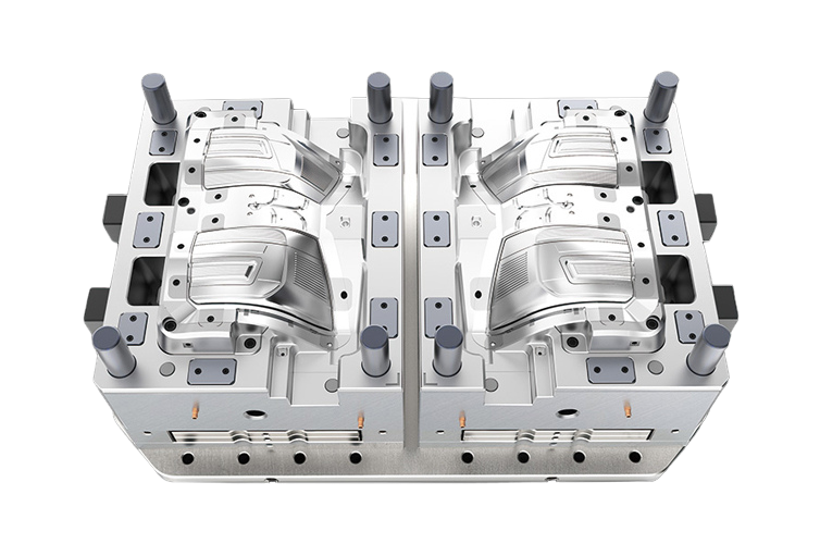
Automotive lighting systems operate under strict regulatory standards, including DOT in North America and ECE in Europe. These regulations demand flawless optical performance and precise beam patterns. Transitioning from tool design to mass production represents a high-stakes engineering phase. Rushing a mold trial or relying on incomplete validation data leads to unacceptable scrap rates. Manufacturers face severe consequences, including optical distortion, assembly fitment failures, and extensive secondary tool modifications. A systematic, phased mold trial checklist bridges the gap between theoretical design and production reality. It ensures the tooling consistently yields defect-free components under standard operating conditions. We will break down the exact protocols required to validate an automotive headlight mold before authorizing full-scale manufacturing.
Engineers must compare the theoretical mold flow data against the physical tool design before mounting the mold in the press. You need to verify gate locations, predicted weld line placements, and venting positions. This comparison helps anticipate potential cosmetic or structural issues during the physical injection phase. Review the mold flow analysis for automotive lamps to confirm that the machined runner sizes and gate diameters match the simulation inputs. Ignoring discrepancies between the digital analysis and the final machined tool leads to unpredictable filling patterns. It often results in trapped gas, short shots, or severe shear stress near the gate.
To properly validate the physical tool against the digital model, execute these specific verification steps on the shop floor:
The trial injection molding machine must mirror the intended mass production environment to ensure seamless scalability. Running a trial on a highly customized lab machine provides false confidence if the production floor uses standard equipment. Confirm the machine tonnage and tie-bar spacing accommodate the mold dimensions comfortably. The shot size of the injection unit should ideally utilize between 30% and 70% of the barrel capacity. Utilizing too little capacity increases residence time, causing optical resins to degrade and yellow. Utilizing too much capacity risks incomplete plasticization and unmelted pellets entering the cavity.
Verify hot runner heating zones, wiring configurations, and controller compatibility. The thermocouple types in the mold must match the machine's temperature controller. Ensure robotic extraction interfaces and end-of-arm tooling (EOAT) are prepared for automated part removal. Manual part removal during a trial introduces inconsistent cycle times, which skews cooling data and dimensional results.
| Equipment Parameter | Trial Machine Requirement | Production Machine Standard |
|---|---|---|
| Clamping Tonnage | Must exceed calculated cavity pressure by 20% | Identical to trial tonnage to prevent flash |
| Screw Design | Low-shear profile for optical PC/PMMA | Low-shear profile for optical PC/PMMA |
| Hot Runner Controller | PID control with 0.1°C accuracy | PID control with 0.1°C accuracy |
| Part Extraction | Automated 3-axis or 6-axis robot | Automated 3-axis or 6-axis robot |
Execute low-pressure mold closing to verify the alignment of core and cavity blocks. This step protects the tool from catastrophic damage if components are misaligned. Confirm the smooth movement of guide pillars, guide bushes, and slider mechanisms. Look for any signs of binding, unusual resistance, or galling on the sliding surfaces. Apply the correct high-temperature grease to moving parts before cycling the tool. Use Prussian blue layout fluid on the parting lines to check for proper shut-off and seal. If the blue transfers unevenly, the tool requires immediate benchwork to prevent flash.
Ejector pins, lifters, and stripper plates must operate smoothly across the full stroke length. They must return to the exact zero position without hesitation. Verify the ejector plate limit switches function correctly to prevent the mold from closing if the pins are not fully retracted. Cycle the mold dry at least 50 times to ensure mechanical stability before introducing any plastic.
Connect all water and oil lines. Pressurize the cooling system to the standard operating pressure before introducing heat to the tool. Micro-leaks in the cooling channels can cause catastrophic defects in optical components. Water seeping onto the molding surface creates severe splay and rusts polished optical cavities rapidly. Hold the system at 6 bar for 15 minutes and monitor the pressure gauges for any drop that indicates a failed O-ring or cracked weld.
Monitor flow rates across all circuits using an inline flow meter. Verify uniform temperature distribution across the mold face using a thermal imaging camera. Check for pressure drops between the inlet and outlet, which indicate internal blockages or restricted flow. Ensure turbulent flow is achieved within the channels, targeting a Reynolds number above 4000, as laminar flow significantly reduces heat transfer efficiency. Proper thermal management directly dictates the cycle time and the dimensional stability of the final lens.
Drain all remaining material from previous runs. During the machine adjustment process, if the machine is stopped for over 30 minutes, perform a complete barrel purge. This prevents resin degradation, which manifests as black specks and yellowing in clear components. Gradually increase hot runner and barrel temperatures to the specific resin manufacturer's recommendations. Avoid sudden temperature spikes that can degrade the polymer chains. Use a dedicated optical-grade purging compound to clean the screw and barrel thoroughly.
Ensure the hot runner system is purged until the extrudate is completely clear and free of bubbles. Temperature stabilization requires patience. Allow the mold and hot runner to soak at the set temperature for at least 15 minutes before initiating the first shot. For Polycarbonate, barrel temperatures typically range from 280°C to 310°C, while PMMA requires a slightly lower profile between 240°C and 270°C. Deviating from these ranges guarantees optical failures.
A systematic trial must isolate and validate clamping, injection, dwelling, cooling, and ejection to identify process bottlenecks early. Monitor clamping force distribution to prevent flash along the parting line. Excessive clamping force crushes venting channels, leading to burn marks. Profile injection speeds to prevent shear stress at the gate. A typical profile starts slow to pass the gate, speeds up to fill the cavity, and slows down near the end of fill to allow gas to escape.
Optimize dwelling pressure to prevent sink marks in thick sections without overpacking the cavity. Validate cooling times to ensure optical clarity and dimensional stability. Removing the part too early causes warpage. Ensure ejection force does not induce stress marks or physical deformation on the warm plastic. Adjust the ejector speed to push the part off the core gently rather than punching it out.
Optical-grade Polycarbonate (PC) and Polymethyl Methacrylate (PMMA) are highly sensitive to shear stress and moisture. When testing a PC PMMA automotive lens mold, verify resin drying times and dew point levels meticulously. PC typically requires drying at 120°C for 4 to 6 hours with a desiccant dryer maintaining a dew point of -40°C. The target moisture content must remain below 0.02% before processing.
Establish initial injection speeds carefully to avoid jetting, where the melt shoots directly into the cavity without adhering to the walls. Set holding pressure and time to compensate for volumetric shrinkage. You must achieve this without inducing birefringence, which is internal stress that distorts light passing through the lens. Use polarized light inspection to detect internal stress concentrations near the gate and sharp corners. If rainbow patterns appear under the polarized filter, the holding pressure is too high or the gate is freezing off too late.
Light guides require extreme precision to ensure total internal reflection (TIR). Any surface imperfection or internal stress disrupts the light path, causing dark spots or uneven illumination. When trialing an automotive light guide injection mold, monitor the transition from injection to holding pressure closely. Overpacking causes stress marks that ruin light transmission. Underpacking causes sink marks that alter the optical path and fail to replicate the micro-optic structures on the mold surface.
Maintain precise mold temperature control to ensure the melt replicates the fine v-cuts and prisms perfectly before freezing. Light guides often require elevated mold temperatures, sometimes exceeding 90°C, to keep the material flowing into the micro-structures. Use a high-response valve gate system to control the melt flow precisely and eliminate vestige marks that could interfere with the LED light source coupling.
The T1 samples must be evaluated under standardized lighting for optical purity. When inspecting parts from an automotive headlight cover mold, look for black specks, silver streaks, and gate blush. Silver streaks indicate incomplete resin drying, while gate blush points to excessive injection speed or a restrictive gate design. Check for yellowing, which signals thermal degradation from excessive barrel temperatures or prolonged residence time.
Inspect the surface finish for flow marks and ensure the high-gloss polish transfers perfectly to the plastic. Use a light box with specific lux levels, typically around 1000 lux, to identify minor optical distortions that naked-eye inspections might miss. Hold the lens at various angles against a grid background to check for refractive errors caused by uneven shrinkage or poor polishing on the cavity steel.
Allow parts to cool for at least 24 hours in a climate-controlled environment set to 23°C and 50% relative humidity. This accounts for post-molding shrinkage before conducting CMM (Coordinate Measuring Machine) inspection. Test the fitment of the auto lamp mold components against mating parts, including housings, bezels, and reflectors. Verify gap and flush tolerances using dedicated holding fixtures that simulate the vehicle mounting points.
Check the profile tolerances of the sealing grooves where the lens meets the housing. Any warpage or dimensional deviation in this area compromises the watertight seal, leading to condensation inside the headlight assembly. Measure the overall length and width of the lens to ensure it falls within the +/- 0.2mm tolerance typically required for exterior automotive lighting.
Identifying the root cause of defects during the T1 trial dictates the success of subsequent tool modifications. Use a structured approach to isolate variables. Change only one parameter at a time, allow the process to stabilize for at least ten shots, and then evaluate the results.
| Defect Type | Root Cause Analysis | Mitigation Strategy |
|---|---|---|
| Weld Lines | Poor melt front fusion during injection due to low temperature or slow speed. | Adjust injection speed profiles, increase mold temperature, or relocate the gate. |
| Sink Marks | Volumetric shrinkage in thick-walled sections lacking sufficient packing. | Optimize holding pressure, extend holding time until gate freeze, and increase cooling time. |
| Burn Marks | Trapped gas igniting under high pressure (diesel effect) at the end of fill. | Check venting depths, clean exhaust slots thoroughly, and reduce injection speed at the end of the stroke. |
| Silver Streaks (Splay) | Moisture in the resin turning to steam, or trapped air in the barrel. | Verify dryer performance and dew point. Increase back pressure to eliminate trapped air. |
| Warpage | Uneven cooling rates between core and cavity, or excessive internal stress. | Balance cooling channel temperatures. Adjust holding pressure to reduce molded-in stress. |
Conduct a Design of Experiments (DoE) to find the upper and lower limits of temperature, pressure, and speed that still yield acceptable parts. A wide process window ensures stable mass production. It reduces dependency on constant operator adjustments when environmental conditions shift slightly. Vary the melt temperature, mold temperature, injection speed, and holding pressure systematically using a fractional factorial design.
Document the boundary conditions where flash, short shots, or sink marks begin to appear. The ideal production setting lies in the exact center of this established window, providing the maximum safety margin against process variations. If the process window is too narrow, the tool requires mechanical modifications to improve flow or cooling before entering mass production.
Pushing for faster cycle times can compromise the dimensional stability and optical clarity of thick PMMA/PC lenses. Removing a thick lens from the mold before the core has sufficiently cooled leads to post-molding warpage. Lock in a cycle time that balances economic throughput with zero-defect quality standards. Calculate the theoretical cooling time based on the thickest wall section of the part.
Use this as a baseline, and adjust based on physical part measurements. Do not sacrifice optical performance to shave a few seconds off the cycle time; the scrap generated will negate any throughput gains. For heavy automotive lenses, cycle times frequently range from 90 to 180 seconds to ensure complete dimensional stability upon ejection.
Document all machine parameters, water temperatures, cycle times, and part weights. Record all observed defects with corresponding photographs. Include explicit recommendations for tool improvements and corrective action plans (CAPA). Detail required steel-safe modifications, such as adjusting draft angles, opening gates, or adding venting.
This report serves as the baseline for T2/T3 trials. It ultimately becomes the standard operating procedure (SOP) for mass production. Without a comprehensive report, subsequent trials rely on guesswork rather than engineering data. Ensure the setup technician signs off on the final parameter sheet, locking the process variables for future runs.
A reliable automotive mold manufacturing supplier provides unedited trial data. This includes short-shot progression boards, honest defect assessments, and comprehensive test details. Evaluate how the supplier communicates failures during the T1 stage. A partner who hides defects or manipulates parameters to produce a few golden samples poses a severe risk to your production launch.
Demand access to the raw parameter sheets directly from the injection molding machine controller. Request a physical short-shot study showing the fill pattern at 10%, 30%, 50%, 80%, 95%, and 99% cavity volume. This visual evidence proves the tool fills evenly and validates the original mold flow simulation.
Vague timelines for transitioning from prototype design to T1 can derail vehicle launch schedules. The same applies to correcting draft angles, gate positions, or separation lines after the first trial. Establish strict Service Level Agreements (SLAs) for engineering changes between trial phases.
Define exactly how many days the supplier has to implement welding, machining, and re-polishing before the T2 trial. Efficient iteration separates capable tooling partners from those who cause severe project delays. Hold the supplier accountable for hitting the agreed-upon dates for secondary trials, ensuring the vehicle assembly timeline remains intact.
An exhaustive automotive headlight mold trial is not merely a milestone to check off. It is the definitive stress test of the tool's engineering, the resin's behavior, and the process's scalability. Tooling approval should only be granted when dimensional accuracy, optical performance, and process stability are proven within a documented, repeatable process window.
A: A T1 trial is the first physical injection of plastic into the completed mold. It verifies basic mechanical function, gate locations, and initial part geometry. Engineers acknowledge that parts are rarely production-ready at this stage. They use T1 data to guide necessary tool modifications and establish baseline processing parameters.
A: A standard trial takes 4 to 8 hours per phase on the machine. However, the entire iterative process from T1 to final approval can take several weeks. This timeline depends heavily on the complexity of required tool modifications, CMM inspection times, and the number of subsequent trials needed.
A: These hygroscopic, optical-grade resins require strict drying protocols. Proper drying prevents moisture-induced defects like silver streaks, bubbles, and loss of light transmissivity. Failing to remove moisture compromises both the structural integrity and optical clarity of the final lens, leading to immediate rejection.
A: A comprehensive report includes machine specifications, injection parameters, temperature profiles, and cooling layouts. It must also document part weights, cycle times, defect logs, and recommended tool modifications. This document serves as the foundation for corrective actions required for the next trial phase.
A: Fixing weld lines involves adjusting mold temperatures and optimizing injection speed profiles to keep the melt front active. Engineers may also need to modify gate locations or adjust wall thicknesses to ensure proper melt front fusion before the material begins to freeze in the cavity.
A: Cycle times vary heavily based on part thickness and material, typically ranging from 60 to 150 seconds. The process prioritizes optical clarity and dimensional stability over sheer speed. Rushing the cooling phase induces warpage and internal stress, which violates strict automotive lighting standards.
A: Mold flow analysis predicts filling patterns, cooling rates, and potential warpage. It allows engineers to identify and correct design flaws digitally before cutting expensive tool steel. This proactive step significantly reduces the number of physical trials required and prevents costly tooling rework.